QTrobot Motion and Actuators
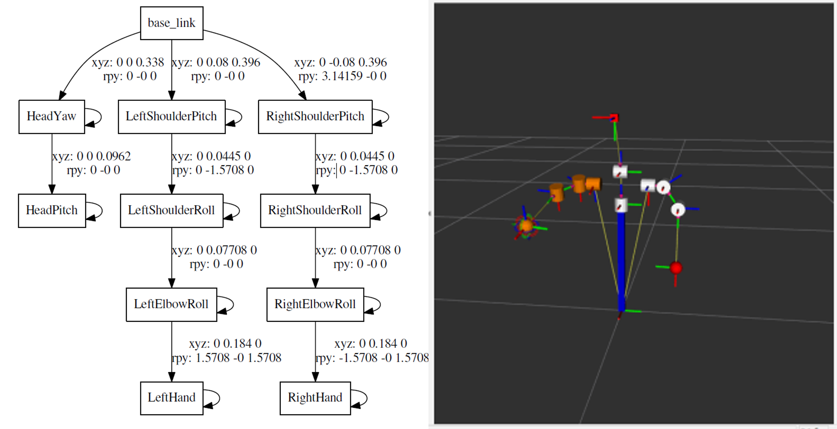
QTrobot has full internal metal structure and eight motors with metal gearbox. Thanks to its advanced compliance motor controllers, QTrobot has flexible joints with overload protection offering a robust platform for for intensive working hours. The smart motors also provide varieties of feedback including position, velocity and torque feedbacks. These powerful motors combined with QTrobot standard ROS motor controllers provide flexible infrastructure for wide varieties of applications: For examples recording and playing gestures, reading motors feedbacks and commanding motors in joint space or using QTrobot inverse kinematics to build more advanced application such as Hand writing. Bellow you can find the kinematics chain and joints name of QTrobot:

Software Interface
The qt_motor is the main software interface for QTrobot actuators. Its implementation follows ros_control paradigm and provides standard ROS interfaces for joint command, joint state, joint trajectory and etc. Beside supporting the relevant standard ros_controllers, qt_motor also implements other custom controllers such as QTGestureController and QTMotorsController via dedicated plugins. The following diagram depicts the architecture of QTrobot motor interfaces:

The qt_motor is running on QTRP during the startup of the robot. Similar to other QTrobot software interfaces, it is an standard ROS node. You can find its configuration files in the node default config path. (e.g. using $ roscd qt_motor/config). Below is a summary explanation of each of QTrobot motors configuration files:
- qtrobot-hardware.yaml: contains low-level motor configurations such as PID value, calibration, main control loop frequency, etc.
- qtrobot-hardware-extra.yaml: contains overwritten parameters for Advanced setup (see standard vs. advanced)
- qtrobot-controller.yaml: contains list and parameters of the controllers
- qtrobot-controller-extra.yaml: contains list and parameters of the extra controllers for Advanced setup (see standard vs. advanced)
- kinematics.yaml: contains some parameters for IKFastKinematicsPlugin solver for left and right arms
QTrobot joints configuration
QTrobot joints are group in three parts: head, right_arm and left_arm. The movement of each joints is limited in software and configured in qtrobot-hardware.yaml along with the applied calibration value using automated motor calibration procedure. Therefore, the value of the joint limits appear in the configuration file may be different from the actual value because they also take the calibration value of each motor into account. QTrobot motor control does not use ROS joint_limits_interface (although one can confgiure and enable it) because the joint limits are set in each motor embedded controller at the startup time. Here are the joint limit values of each joint:
-
head
- HeadYaw [min: -90.0, max: 90]
- HeadPitch [min: -15.0, max: 25]
-
right_arm
- RightShoulderPitch [min: -140.0, max: 140.0]
- RightShoulderRoll [min: -75.0, max: 7.0]
- RightElbowRoll [min: -90.0, max: -7.0]
-
left_arm
- LeftShoulderPitch [min: -140.0, max: 140.0]
- LeftShoulderRoll [min: -75.0, max: 7.0]
- LeftElbowRoll [min: -90.0, max: -7.0]
Please notice that, the joint limit is different from collision control and this does not mean that the QTrobot has self collision awareness when moving its parts! The embedded controller of each motor ensure that each joint separately does not exceed the limit. However the overall generated trajectory may collide other robot's parts.
Reading motors feedback
QTrobot uses standard ROS JointStateController and publishes motor feedbacks such as position, velocity and effort values on /qt_robot/joints/state. To access these values, you can simply subscribe to this topic. Here is an example of reading joints state values from command line:
rostopic echo /qt_robot/joints/state

---
header:
  seq: 1911781
  stamp:
    secs: 1634639561
    nsecs: 334769943
  frame_id: ''
name: [HeadPitch, HeadYaw, LeftElbowRoll, LeftShoulderPitch, LeftShoulderRoll, RightElbowRoll,
  RightShoulderPitch, RightShoulderRoll]
position: [0.8999999761581421, -43.29999923706055, -16.899999618530273, 89.30000305175781, -76.19999694824219, -22.100000381469727, -88.9000015258789, -80.5]
velocity: [0.0, 0.0, 0.0, 0.0, 0.0, 0.0, 0.0, 0.0]
effort: [-113.0, -75.0, 12.0, -13.0, 37.0, -13.0, 0.0, 12.0]
To learn more about motors and reading feedback from code, you can follow our Python QTrobot motors tutorial.
Commanding motors
QTrobot motors are grouped in different parts as it's described in joint configuration. To commands a motor in a joint space, you need to use the interface for the corresponding part which is of the following:
- Publishing to
/qt_robot/head_position/commandtopic for head motors - Publishing to
/qt_robot/left_arm_position/commandtopic for left arm motors - Publishing to
/qt_robot/right_arm_position/commandtopic for right arm motors
For example to move robot's HeadYaw joint to looks 45° degree to its left side, you can try the following command from terminal:
rostopic pub /qt_robot/head_position/command std_msgs/Float64MultiArray "layout:
  dim:
  - label: ''
    size: 0
    stride: 0
  data_offset: 0
data: [45, 0]"
- to easier write the ROS publishing command in a terminal, start writing your command (e.g.
ros pub /qt_robot/) and pressTABfew times to autocomplete the command. - You can not send command to only one joint! in the above example we are actually sending
0°command to theHeadPitchtoo. - Data array is defined as chain of motors (e.g. left arm => data:
[<LeftShoulderPitch>,<LeftShoulderRoll>,<LeftElbowRoll>])
To learn more about commanding motors you can follow our Python QTrobot motors tutorial.
QTrobot gesture controller
The QTGestureController plugin provides ROS interfaces to manage QTrobot body gestures such as listing, playing and recording gestures. QTrobot comes with some pre-recorded gestures, which are located and categorized in QTRP under ~/robot/data/gestures/ folder. However one can easily record a new gesture by simply activating and moving robot parts (head, right arm and left arm). You can play any gesture using one of the following methods:
- Using Educator tablet app
- Publishing to
/qt_robot/gesture/playtopic - Calling
/qt_robot/gesture/playservice
For example, you can open a terminal (on QTPC) and try the following command to play the happy gesture
rostopic pub /qt_robot/gesture/play std_msgs/String "data: 'QT/happy'"
QTrobot gestures may contains all parts or can be recorded using only one part (e.g. head). However for the time being, you cannot play two gestures concurrently. The gesture controller does not accept other requests for playing new gesture when it is already busy playing another gesture!
What are QTrobot gesture files?
The QTrobot gestures contain robots joints position's waypoints and their corresponding timestamps. The joint positions are recorded in 20Hrz and formatted in XML file (e.g. QT/bye.xml) with some other information such as duration of the gesture and the robot parts which are involved in playing the gesture. After recording, the gesture file can be manually post processed (if required), for example, to remove the trailing delay by simply delete the unnecessary waypoints from the file. Bellow is an example of QTrobot gesture file:
<?xml version="1.0" encoding="utf-8" standalone="yes" ?>
<gesture>
    <name>QT/bye</name>
    <parts>
        <part>right_arm</part>
    </parts>
    <duration>5.54</duration>
    <waypoints count="97">
        <point time="1558971402671926152">
            <RightElbowRoll>-31.90</RightElbowRoll>
            <RightShoulderPitch>-88.60</RightShoulderPitch>
            <RightShoulderRoll>-59.30</RightShoulderRoll>
        </point>
        <point time="1558971402704626777">
            <RightElbowRoll>-30.60</RightElbowRoll>
            <RightShoulderPitch>-88.60</RightShoulderPitch>
            <RightShoulderRoll>-60.60</RightShoulderRoll>
        </point>
...
How to record a new gesture?
Recoding a gesture is done by moving the robot parts by hands and store the joint positions. This involve the following generic procedures:
- putting the desired motors in the idle mode (release the stiffness of the motors)
- moving the motors by taking the corresponding parts (e.g. right_arm) in your hand and to generate desired gesture
- store the motor's position waypoints and reactive the motors stiffness
To record a gesture, you can use one of the following tools:
- Using Educator tablet app
- Using qt_gesutre command line tool
- Manually using
QTGestureControllerandQTMotorsControllerservice calls
Using QTrobot Educator app (recommended)
Indeed the easiest and quickest way to record a gesture is to use QTrobot Educator tablet app. You can follow our Record a new gesture using tablet tutorial to see how easily you can record a new gesture.
Using QTrobot qt_gesutre command line tool
By default the qt_gesture.py script should be installed on QTRP under ~/robot/code/software/tools/qt_gesture_tool. Anyway, if you cannot find it, just simply update the software repo using git pull.
For example to record a gesture using QTrobot's right arm, follow these steps:
- run the
qt_gesture.pycommand with the name of your gesture (e.g. mygesture) and give the"right_arm"as the part list:
~/robot/code/software/tools/qt_gesture_tool/qt_gesture.py record mygesture "right_arm"
- press enter to START recording.
- you will notice that robot's right arm is loose. take the arm and move it around to generate your desired gesture.
- when it's done, press enter again to STOP recording
Your gesture should be stored in ~/robot/data/gestures/mygesture.xml. You can play and test your gesture.
Tips for recording better gestures
For generate and record safer and smoother gestures, please pay attention to the following tips carefully:
When recording a gesture, never hit the robot parts to each other or to the QTrobot's body.Do not move the arms or head so fast and avoid sharp and shaky movements. Move it naturally and smoothly. Due to safety feature implemented in the gesture controller, the fast movement will be slow down automatically and you would not get a desired gesture.
Do not move the robot head so fast up and down. This may apply excessive force to the neck motor joints when playing the gesture!
It is always easier to record gestures using an assistant: one person to control the Tablet app/command line tool and the other person move the robot parts.
QTrobot Inverse kinematic
QTrobot parts can be controlled in cartesian space from example using MoveIT Motion Planning Framework. Generally, in cartesian space, you do not command each joints seperately, instead you ask robot to move its end efecctor (for example right hand) to a desired position in cartesian coordinate using X, Y and Z position with respect to a reference point. To do this you need some more knowledge and setup which are covered in the following sections.
QTrobot URDF
The URDF (Universal Robot Description Format) model is a file or collection of files that describe a robot's physical description such as the motors mechanical position and orientation, the links between motors and etc. The URDF file can be used for visualization of the robot, calculating the inverse kinematics or motion planning in ROS. Following is a description and simple visualization of QTrobot's URDF:
You can find the QTrobot URDF files using the following links: qtrobot.pdf and qtrobot_urdf.zip. To visualize the URDF model, you can use ROS urdf_tutorial on QTPC using the following command:
roslaunch urdf_tutorial display.launch model:=qtrobot.urdf
QTrobot motors standard vs. advanced setup
QTrobot provides two different setups (standard and advanced) which can be configured depending on the use cases and applications. The default setup is standard which provides the JointGroupPositionController to command motors using joint position commands. On the contrary the advanced setup is intended for applications which require more advanced motor controls using inverse kinematic, MoveIT Motion Planning Framework, JointTrajectoryController and etc. Bellow is a summary of the configuration of each setup:
| Position unit | Control loop frequency | Controllers and interfaces | |
|---|---|---|---|
| Standard | degree | 2Hrz |
|
| Advanced | radian | 30Hrz |
|
For most of the human-robot-interaction applications, the standard setup should be more than enough unless you want to use inverse kinematic in your scenario similar to our QTrobot hand writing tutorial. In this case, to enable the advanced setup,
- simply open
~/robot/autostart/start_qt_motor.shon QTRP - change the line regarding launching qt_motor as follows:
roslaunch qt_motor qt_motor_advanced.launch - restart the QTrobot
QTrobot's ikFast plugin and MoveIt
We have already created the inverse kinematic solver of QTrobot's left and right arm using IKFast Kinematics Solver. You can find these plugins in ~/robot/code/software folder on QTRP and QTPC or get them from QTrobot github software repository. Perhaps the easiest way to learn how to use the MoveIt framework wit QTrobot is to to follow our QTrobot hand writing tutorial. In this tutorial you will see :
- how to prepare the setup for MoveIT
- how to visualize the robot's state in ROS Rviz
- How to use
moveit_ros_move_groupfor motion planning - How to use QTrobot's right arm for hand writing
- How to ask QTrobot to draw shapes created in SVG file
Take a look at QTrobot hand writing demo in action: